As the design of contact lenses and interocular lenses has become more complex, more accurate 3D measurement technologies are needed to reliably produce the master forms needed for manufacturing.
The global contact lens industry is undergoing major changes as shifting market demographics help to drive new technological development of contact lenses and interocular lenses (IOLs). New versions contain surface structures at the nanometer level and aspheric designs with spherical and cylindrical shapes in differing axes. These new structured lens designs are geometrically more complex and difficult to manufacture, resulting in a higher number of iterations and rework that drive up manufacturing costs.
Traditional measurement methods such as Fizeau interferometers and 2D stylus profilers do not provide sufficient accuracy or the comprehensive 3D measurements needed for the manufacture of these nanometer features that control the geometry of the finished lenses to the required tolerance levels. A new generation of noncontact optical profilers provides complete 3D surface measurements to a higher level of accuracy at high speeds. A typical lens manufacturing plant that produces 100 pins per year can expect to save around $1 million per year by reducing the number of pin iterations and rework.
Contact Lens Trends
The original focus in the contact lens industry was on consumers under 25 years of age with near-sightedness that could be corrected with spherical lenses. However, the dynamics of an aging population have changed this, and today the fastest growing segment of the contact lens and intraocular lens market is in the 40+ age category. This change is being driven by two primary diseases, namely presbyopia (a gradual hardening of the lens of the eye that limits the ability to focus to short distances) and cataracts (a clouding of the optical lens in the eye). Since both cataracts and presbyopia are age-related conditions, they generally occur together in later life. People over the age of 55 who have traditionally worn contact lenses typically suffer from nearsightedness as well as presbyopia so they typically require bifocal contact lenses. People undergoing cataract surgery also typically will suffer from presbyopia and therefore will require bifocal intraocular lenses.
Bifocal lenses can be designed in several different ways. The predominant methodology today is to create lenses with alternating optical powers structured within a concentric circular pattern. Each concentric lens is structured for either distance or near vision and the eye looks through both distance and near powers at the same time. The eye selects the correct power choice based on the distance to the object the eye is focusing on thereby providing continuous near and far vision.
To further complicate matters, many older patients also need correction for astigmatism, where the ocular system needs one power of correction in one axis and another power of correction in another axis. Toric lenses that correct for astigmatism generally have two powers orthogonal to each other and the corrective lens must be held static to maintain the proper angular orientation between the two powers. Two different methods for maintaining angular stabilization are a double slab-off and a prism ballast, both of which use gravity and blinking forces of the eye to hold the lens in place.
Manufacturing Challenges
As a result, the market is being driven toward contact lenses and IOLs that contain both surface structures at the nanometer level and aspheric designs with spherical and cylindrical shapes in differing axes. Cast molding is the primary manufacturing method used for producing these more complex lens designs. This method utilizes front and back curve molds that typically are molded from a tool commonly referred to as a “master pin” that is machined using a diamond blade. This master pin contains the nanometer-level structures that must be accurately replicated on the lens. Different master pins are used to create the front and back curve molds. The front and back curve molds are assembled in mold inserts. A polymer is injected in the mold and thermally cured. The lenses are then hydrated where they absorb 20% to 70% water by mass.
The master pins wear out after producing a number of molds, so contact lens manufacturing plants often must build new ones. Before each master pin can be used to make production molds, it must be first be tested by building a trial mold that is used to produce a limited pilot run of lenses. The lenses are then tested to see if they provide the right prescription. In most cases the first batch of lenses does not produce the right prescription, so the pin must be re-engineered and re-machined, new molds must be produced, and finally a new batch of lenses must be molded and tested. In a typical lens manufacturing plant, it can easily take two to six iterations of this process to produce lenses that meet the prescription. Even after the lenses pass the test, problems later develop in many of the pins that require the pin to be re-worked an additional time.
One of the main reasons that it is necessary to produce so many iterations of the master pins is because there are limitations in the methods available to measure the lenses. For pins producing spherical lenses, the current metrology solution is a Fizeau interferometer. Fizeau interferometers measure the form and shape of the lens surface profile and compare the radius curvature to a fixed reference. One of the limitations of this approach is the need to produce a golden reference for each lens prescription. Another limitation is that Fizeau interferometers are laser-based, so they are limited to a maximum step height measurement of one-fourth of the laser wavelength or approximately 160 nanometers. Structured lenses being manufactured today contain step heights greater than 160 nanometers, so Fizeau interferometers are not an appropriate metrology solution for these lenses.
For aspherical and stepped surfaces, the current metrology solution is a 2D stylus device. In ophthalmic applications the stylus is generally scanned in one X and one Y direction to capture the asymmetric nature of the lens and measure the individual step heights of structured lenses. Stylus measurements are contact-based and are slow compared to non-contact optical methods. The operator also has to position the stylus device manually. If the operator does not correctly position the stylus to intersect the apex of the lens, inaccurate measurements will be obtained. For structured surfaces it is insufficient to measure one X and one Y position, so the entire lens may need to be mapped. However, the 2D stylus is too slow for this task and risks damaging the surface being measured. The diameter of the tip also limits the features that can be measured. For example, if the stylus tip is 5 microns in diameter it cannot measure features smaller than 5 microns.
Emerging 3D Measurement Methods
A newer, quantifiable and repeatable method involves the use of white light interferometry, also known as optical profiling, to accurately measure the complete 3D surface profile of the lens. In an optical profiler, light approaching the sample is split and directed partly at the sample and partly at a high-quality reference surface. The light reflected from these two surfaces is then recombined. Where the sample is near focus, the light interacts to form a pattern of bright and dark lines that track the surface shape. The microscope is scanned vertically with respect to the surface so that each point of the test surface passes through focus. The location of the maximum contrast in the bright and dark lines indicates the best focus position for each pixel, and a full 3D surface map is generated. Figures 1 through 3 show examples of the 3D surface maps produced by white light interferometry.

Figure 3: Optical profiling 3D characterization of a used interocular lens revealing wear at lens edge.
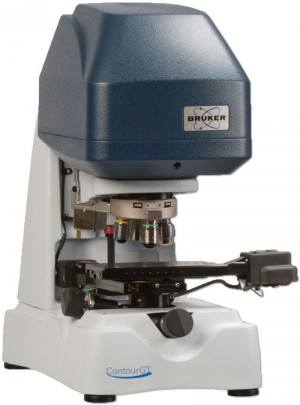
An advantage of the optical profiler is that a complete 3D surface measurement provides a much more complete representation of the lens surface than is produced via a 2D stylus. This can greatly reduce the need for additional iterations and rework. Optical profilers have no step height measurement limitations so they can measure all types of lenses. In the latest generation of instruments, the ContourGT family of white light interferometers (Bruker-Nano Surfaces Division), 64-bit software and multicore processing provide a faster and more intuitive software workflow while facilitating a higher rate of data collection. A patented illumination source provides increased light throughput, speeding up measurement time while simultaneously providing enhanced data collection (Figure 4).
The benefits of white light interferometry were demonstrated in a recent application at a major lens manufacturing facility. The plant produces 100+ master pins per year to produce 48 different designs ranging from +6.0 to +30.0 diopters in 0.5 diopter increments. Manufacturing costs vary depending upon manufacturing region; however, an average cost per iteration is in the order of $2,500, including fully loaded engineering and small batch manufacturing costs. Using 2D stylus metrology, the plant required four iterations for the average master pin and an additional 67 pins had to be reworked after being accepted for production. A total of 667 iterations were on average required to produce the 100 pins per year, for a total cost close to $1.7 million dollars per year.
Using white light interferometry, the number of iterations required before production acceptance was significantly reduced as were the number of pins requiring rework after production acceptance. The benefits and savings associated with employing white light interferometry were such that the initial capital outlay for the tool is paid within a matter of months.
Bruker-Nano
Tucson, AZ
(520) 741-1044


